


ATC Pedestal Install Guide
This is the central outline that helps to point you to the right articles and guides for installing our ATC Pedestals. We’re always working on improving so please reach out if there’s something that needs improving.
Which are you installing?


ShopSabre Drop-in Pedestals
Only for ShopSabre CNC routers. Install ATC Pedestals with a specific base to make swapping easy.
Modular ATC Pedestals

🚨 Disclaimer: We’ve done our best to give you the best guide we can. Every machine can have slight differences – so be aware and adapt. DO NOT blindly trust any of our guides - think through each step yourself!
👋 Skim the whole guide before starting!
1) Measure Tools
Before removing your ATC Rack or Tool Probe
Setup and Measure Tool lengths with your Tool Height Probe:
-
.500” (1/2) Flat End Mill in Tool holder as T1
-
#8 Drill in Tool Holder as T2
2) Backup your WinCNC Folder (ShopSabre)
-
Open C:\WinCNC on your CNC PC.
-
Copy this folder and Paste it somewhere safe. E.G. – A USB flash drive or your Desktop.
-
Then rename it to WinCNC - BACKUP.
3) Download CAD/CAM Files for your Machine
If something doesn’t look right, do not run the file! Get in touch and we’ll make sure things are right first.
Generic
Generic 5 or 10 Tool Layout (Bed X: 60")
- Table Width: 60" (bed top edge to edge)
ShopSabre
Standard ShopSabre CNC Router layouts - under each item are confirmation items to make sure you have the right file.
ShopSabre PRO 404 & 408 (Bed X: 60") - up to 12 tools
- Table Width: 60" (bed top edge to edge)
- Table top thickness is at least: .74"
ShopSabre PRO 510 (Bed X: 72") - up to 14 tools
- Table Width: 72 (bed top edge to edge)
- Table top thickness is at least: .74"
ShopSabre IS 408 (Bed X: 65") - up to 13 tools
- Table Width: 65" (bed top edge to edge)
- Table top thickness is at least: .74"
ShopSabre IS 510 (Bed X: 75") - up to 15 tools
- Table Width: 75" (bed top edge to edge)
- Table top thickness is at least: .74"
ShopSabre IS 612 (Bed X: 85") - up to 17 tools
- Table Width: 85" (bed top edge to edge)
- Table top thickness is at least: .74"
4) Remove Existing ATC Tool Rack & Z-Probe
-
Remove anything that is mounted in the area of the ATC rack at back of the machine.
5) Screw HDPE Inserts in ATC Rack Slot
-
Use provided Flat 13mm diameter ¼-20 screws to attach HDPE infill parts in ATC Rack slot using existing ATC Rack mount holes. The HDPE parts will be proud of your bed, we will face this down to flush.
6) Machine HDPE
-
Manually tool change and tell the machine which tool you’re using:
-
Insert T2 - #8 drill into the spindle by hand.
-
Type L110T2 in WinCNC to tell the machine you’ve inserted T2 in the spindle. Press Enter - That updates in lower right corner of WinCNC.
SET X0Y0Z0-
Set Z0 to the top of your table.
-
Turn off Soft Limits – type L21 into WinCNC, Press Enter
-
Jog using keyboard or pendant with T2 to the existing ¼-20 ATC Rack Bolt Hole.
-
Align the drill bit with the center of any existing bolt hole in the ATC Rack pocket.
-
Raise the tool in Z if needed but do not change Y as you jog to the left edge (-X) of your CNC Table.
-
Make sure to do this cautiously as Soft Limits are turned off.
-
With the Y aligned to the bolt-hole center and X aligned to the left of the table (-X), hit the XY Zero button on WinCNC to set your origin here.
-
With a tape measure, confirm the width of your table in X is the same as our CAD file download details for the machine that you downloaded previously.
-
Insert the tool holder into the spindle you previously set the height of as T1 - End Mill to face HDPE.
-
Type L110T1 in WinCNC to tell the machine you’ve inserted T1 in the spindle. Press Enter - You’ll see that update in the lower right corner of the program.
-
Turn off Soft Limits – type L21 into WinCNC, Press Enter
-
Preview the downloaded file in WinCNC and jog the area that will be machined and drilled to confirm fit on the table.
-
Turning off Soft Limits means you can crash or drive the gantry off the back of the machine on IS & newer PRO. Work with caution!
-
-
Open and Run the Machining Operation for HDPE Facing.
7) Drill Operation
-
Switch the tool to T2 - the #8 drill by hand.
-
Type L110T2 in WinCNC to tell the machine you’ve inserted T2 in the spindle. Press Enter - You’ll see that update in the lower right corner of the program.
-
X0Y0 and Z0 should remain the same as the previous operation.
-
Turn off Soft Limits – type L21 into WinCNC, Press Enter
-
Open, preview, and jog the location of the drilling coordinates to make sure they clear any hardware that may be in your table (bolt heads etc).
-
Turning off Soft Limits means you can crash or drive the gantry off the back of the machine on IS & newer PRO. Work with caution!
-
-
Run the Drilling Operation.
8) Tap Frame/Table for Base Mounting
After you’ve machined the HDPE flush and drilled your base patterns, the best method is to hand drill and tap into the steel frame. If you have an MDF top this is necessary. A phenolic top can be tapped directly, however attaching to the steel frame is the best option – and the hardware we’ve included is suited for that.
-
Use a hand-powered drill and insert the #8 drill to drill into the steel below for each of your mount holes.
-
Keep in mind that the alignment pin holes do not need to be hand drilled (these are shallow holes).
-
Use the M6 x 1 tap to hand tap the steel frame (and table material above it). Tap fluid like Tap Magic or a little oil is recommended for tapping.
-
There should be 1-2 tap holes for your Z-probe stand as well. This may not reach into steel depending on your machine model. (It takes very little force in use).
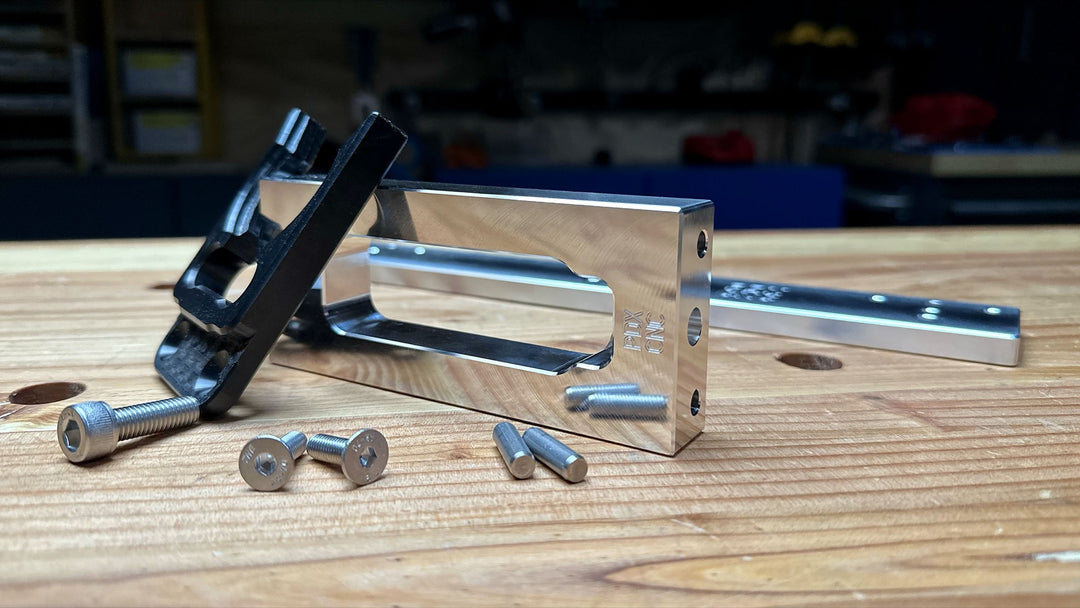
9) Assemble Parts
Attach Bases to Table
-
Starting at the right of your machine (+X), insert two dowel pins into the table for each Base.
-
Use 2ct - 5mm dowel pins & 2ct - M6 x 35mm SHCS - per Base
-
Work your way to the left side (-X), the order of Bases is not important.
-
Hand tighten (don’t overtighten) M6 SHCS to secure Bases to table with 5mm Allen wrench.
-
Only 2 SHCS are needed per Base.
Attach Risers to Bases
-
Use 1ct - M8 SHCS & 2ct - 5mm dowel pins per Riser.
-
Insert Dowel Pins into Base, then drop Riser onto dowel Pins with logo facing Y+.
-
Use 6mm Allen wrench with ball end to tighten each Riser to its Base.
-
Use the short end of Allen wrench for a bit more torque. Hand snug is good.
Attach Forks to Risers
-
Use 2ct - 6mm Flat Head Screws to attach 1ct - ISO30 Tool Fork to each Riser.
-
Tool Fork should be open towards Y+ or the back of the machine.
-
Snug each screw down, no need for heavy force.
-
The extra white Tool Fork is a “Spare Tire” in case you break one. We sell ATC Forks here. 😉
Attach Z-Probe Stand to Table
-
Use 2ct - 5mm Dowel Pins into the table
-
Drop Z-Probe Stand on Top of Pins
-
Attach with M6 SHCS (1 or 2ct depending on style)
-
If your probe wire does not reach to new location you may need to hand-drill a new hole in the table to create a better path.
Attach Z-Probe to Probe Stand
-
Depending on your Probe model:
-
ALU Rectangle Probe - Use previous screws to attach to stand
-
Cylinder Body Probe - Use provided 2ct - M4 SHCS
10) Update WinCNC Files
To add (or subtract) tool positions to your ShopSabre CNC machine, you'll need to make some changes to WinCNC. After changing and saving these files, restart WinCNC. Homing will be required after.
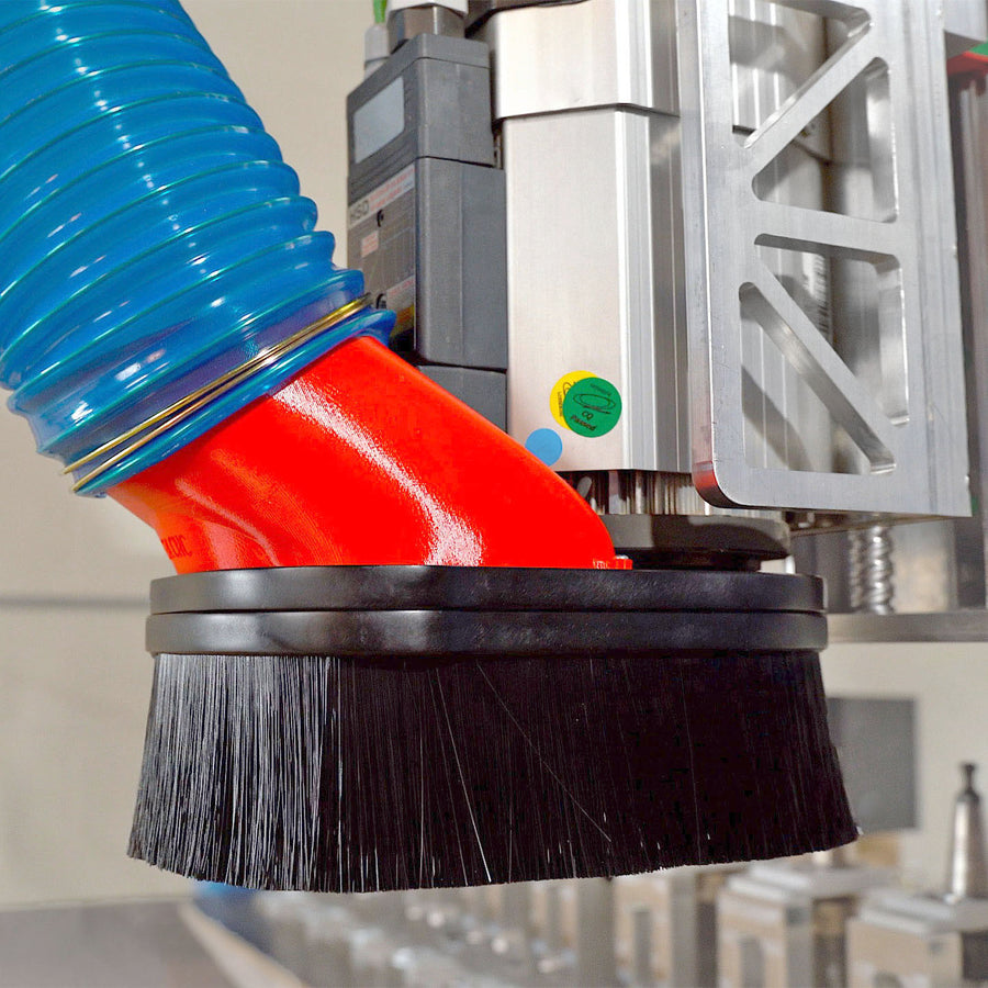
11) DISABLE THE DUST DOCK
Have the Dust Dock? You’ll need to disable it as it won’t allow us to use the full width of the table. You’ll also need to remove the Yellow Dust Dock arm for full travel capacity.
12) Change Z-Probe Position
Your Z-probe is now in a new position. You need to tell WinCNC where that is.
After changing and saving WinCNC files, restart WinCNC. Homing will be required after.
13) Calibrate Positions
Changing ATC tool positions will impact tool changes. Our self-centering ATC Forks and precision dowel pin-aligned Bases, and Risers prevent position shifting. When installing, ensure each position aligns where the machine expects it by following a deliberate jogging procedure.
If you're adding our ATC Pedestals to your machine, you'll want to carefully make sure each position is where your machine thinks it is. It is not a difficult process, you need to use - surgeon-like-focus - to jog your machine to each position.
14) Tool Height All Tools
After moving your Tool Height Probe you want to make sure to re-height every tool. During the first auto-tool heighting, make sure everything clears as expected. Hover over ESC or E-stop.
Try to tool change each position with a dummy tool.
ShopSabre Drop-in Install Guide
1) MEASURE TOOL
Before removing your ATC Rack or Tool Probe
Have one Measured Tool using your existing Tool Height Probe:
-
Any 2, or 3 flute or drill will work. Don’t use a flycutter or insert tool.
2) Backup your WinCNC Folder
-
Open C:\WinCNC on your CNC PC.
-
Copy this folder and Paste it somewhere safe. E.G. – A USB flash drive or your Desktop.
-
Then rename it to WinCNC - BACKUP.
3) Remove Existing ATC Tool Rack & Z-Probe
-
Unbolt and remove old rack.
-
Find awkward place in your shop for these large piece(s) of metal.
4) Assemble Parts
(Tools needed: 3/16”, 4, 5, 6mm Allen wrenches)
A) Attach Bases to Table

-
Orient Base labeled A on left most side with Letter on X- (left).
-
Align Pedestal Base “Slots” with holes used to bolt old rack.
-
Use 3/16 Allen wrench to loosely attach 1/4-20 SHCS into holes used for old rack.
-
Repeat loose screw method for Base B to the right of A. It should slide right up next to A.
-
If you have 10 positions:
-
Continue with the same methods to add Base C to the right of B followed by Base D to the right of C.
-
Pull all Bases to the Y- side and tight touching each other. Tighten down ¼-20 SHCS to table.
B) Attach Risers to Bases
-
Use 1ct - M8 SHCS & 2ct - 5mm dowel pins per Riser.
-
Insert Dowel Pins into Base, then drop Riser onto dowel Pins with logo facing Y+.
-
Use 6mm Allen wrench with ball end to tighten each Riser to its Base.
-
Use the short end of Allen wrench for a bit more torque. Hand snug is good.
C) Attach Forks to Risers
-
Use 2ct - 6mm Flat Head Screws to attach 1ct - ISO30 Tool Fork to each Riser.
-
Tool Fork should be open towards Y+ or the back of the machine.
-
Snug each screw down, no need for heavy force.
-
The extra white Tool Fork is a “Spare Tire” in case you break one. We sell ATC Forks on our Shop 😉 atcpedestal.com
D) Attach Z-Probe Stand to Base A
-
Use 2ct - 5mm Dowel Pins into the Left end of Base A.
-
Drop Z-Probe Stand on top of pins
-
Attach with M6 SHCS (1 or 2ct depending on style)
-
If your probe wire does not reach to new location you may need to hand-drill a new hole in the table to create a better path.
E) Attach Z-Probe to Probe Stand
-
Depending on your Probe model:
-
ALU Rectangle Probe - Use previous screws to attach to stand
-
Cylinder Body Probe - Use provided 2ct - M4 SHCS (3mm Allen wrench)
5) Change Z-Probe Position
Your Z-probe is now in a new position. You need to tell WinCNC where that is.
After changing and saving WinCNC files, restart WinCNC. Homing will be required after.
6) Calibrate Positions
Changing ATC tool positions will impact tool changes. Our self-centering ATC Forks and precision dowel pin-aligned Bases, and Risers prevent position shifting. When installing, ensure each position aligns where the machine expects it by following a deliberate jogging procedure.
If you're adding our ATC Pedestals to your machine, you'll want to carefully make sure each position is where your machine thinks it is. It is not a difficult process, you need to use - surgeon-like-focus - to jog your machine to each position.
7) Tool Height All Tools
After moving your Tool Height Probe you want to make sure to re-height every tool. During the first auto-tool heighting, make sure everything clears as expected. Hover over ESC or E-stop.
Try to tool change each position with a dummy tool.
That’s it! Enjoy!
We have an ever-expanding line of CNC Things 👇